IN Brief:
- The EKO family covers currents from 50A to 1100A and operating voltages up to 1000VDC.
- Breaking capacity reaches 50kA DC, with selected versions supporting 1250VAC and 100kA AC.
- High energy DC systems are increasing demand for coordinated protection across batteries, converters, conductors, and service isolation.
Schurter has extended its EKO high voltage fuse platform across battery storage, electric vehicle charging, uninterruptible power supplies, industrial drives, renewable energy equipment, and other high energy conversion systems.
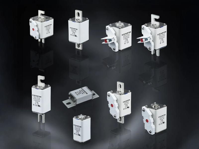
The square body family covers rated currents from 50A to 1100A and operating voltages up to 1000VDC, while selected versions also support 1250VAC. Schurter specifies a DC breaking capacity of 50kA, rising to 100kA AC on selected devices.
Ceramic bodies and tin plated copper alloy connections provide the mechanical and thermal foundation, with mounting options spanning flush end versions, DIN rail formats, US style bolted tags, and bolt on configurations. Optional indication and microswitch arrangements allow a blown fuse to be reported directly to control or maintenance systems.
Operating temperature extends from -40°C to 125°C, and the range is offered against IEC, UL, and GB/T requirements alongside CE, RoHS, and REACH compliance. Final equipment approval will still depend on the assembled system, conductor sizes, enclosure, spacing, and the manner in which the fuse is applied.
High voltage DC protection requires more than matching a fuse to the nominal load current. The device must carry continuous current and short duration inrush without nuisance operation, then interrupt a fault before cables, busbars, cells, contactors, semiconductors, or enclosures exceed their thermal and mechanical limits.
Unlike an AC waveform, a DC fault does not pass through a natural current zero during each cycle. Arc interruption therefore depends more heavily on the internal fuse construction, system voltage, available fault current, and the energy stored in batteries, capacitors, and inductive elements around the protected branch.
Battery storage introduces further variation because prospective fault current changes with chemistry, state of charge, pack arrangement, interconnect resistance, and the number of parallel strings. Charging systems and converters can add capacitive discharge or reverse current paths, while maintenance procedures may require a separate manual isolation device.
Protection coordination consequently extends across the fuse time current curve, cable withstand, contactor capability, semiconductor short circuit limits, and electronic shutdown behaviour. A controller may interrupt some faults rapidly, but a passive fuse remains available when control power, firmware, communications, or the sensing chain has already failed.
ABB’s move into a broader range of DC conversion technologies through Advantics reflects the continued spread of direct current systems across mobility, energy, and industrial equipment. As those buses become larger and more common, fuse selection moves closer to the centre of system architecture and certification.
Installation conditions can alter the usable current rating substantially. Conductor cross section, terminal torque, enclosure airflow, neighbouring heat sources, and repeated load cycles all influence fuse temperature, while poor contact resistance may create local heating that remains invisible to the main control system.
Indication contacts improve serviceability by identifying a failed branch and allowing the controller to record the interruption. They do not provide the detailed current history available from an electronic fuse, so many high power systems will continue to combine semiconductor monitoring with a conventional fuse capable of clearing high energy faults independently.
The 50A to 1100A span allows one family to cover smaller charging assemblies, modular power equipment, and larger storage or industrial installations. That continuity can simplify documentation and sourcing, although each variant must still be selected around fault current, working voltage, ambient conditions, conductor protection, and downstream energy limits.
A fuse occupies little space in the overall system diagram, yet its interruption behaviour can determine whether a failure remains within one branch or spreads through the cabinet. The EKO range addresses that point with a platform designed for high DC voltage, substantial continuous current, and international deployment.