IN Brief:
- Late-stage inverter and vehicle testing often requires accurate current measurement without disconnecting high-current conductors.
- CT200SA and CT500SA provide 1MHz and 500kHz bandwidth respectively, with specified accuracy of ±0.09% of reading plus 0.01% full scale.
- Both devices connect directly to power analysers and waveform instruments for EV, renewable-energy, HVAC, and data-centre power testing.
Yokogawa Test & Measurement has introduced two split-core AC/DC current sensors intended to bring higher measurement accuracy into test environments where installing a conventional through-hole transducer is impractical. The CT200SA and CT500SA cover rated currents of 200A and 500A respectively, while combining clamp-on installation with bandwidth suitable for inverter and power-conversion measurements.
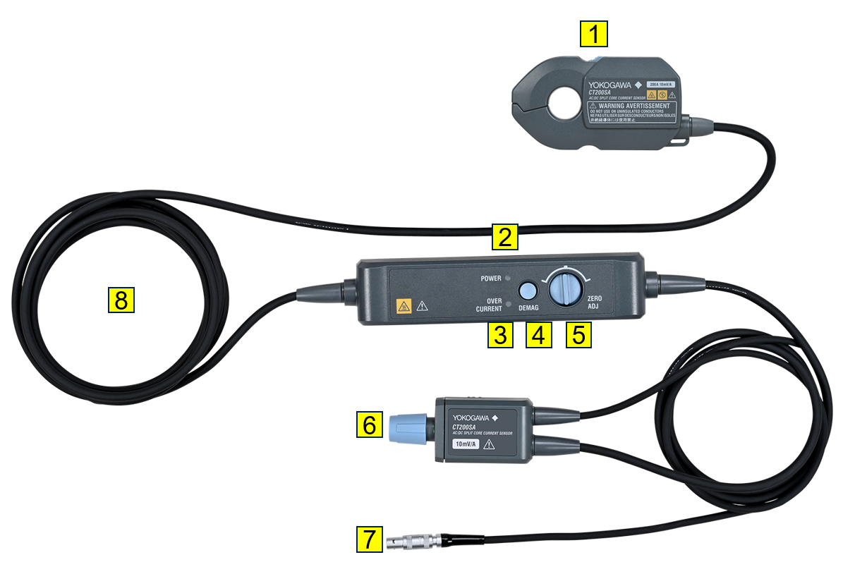
Both devices are scheduled for release on 9 September. Their main sensor units measure 110mm × 62mm × 25mm and use a single-button mechanism to open the magnetic core, allowing engineers to fit the sensor around an existing conductor without disconnecting the circuit. An M4 mounting hole and cable-tie slot are provided to hold the sensor in position during longer test sequences.
Accuracy is specified at ±0.09% of reading plus 0.01% of full scale within a 23°C ±5°C temperature range. The CT200SA provides a -3dB bandwidth from DC to 1MHz, while the higher-current CT500SA extends from DC to 500kHz. Both retain phase accuracy of ±0.1° between 0.1Hz and 1kHz.
That combination addresses a measurement problem that becomes more awkward as power electronics reach the later stages of product development. A conventional closed-core current sensor can provide high accuracy, but the conductor has to pass through its aperture. Once an inverter, electric drivetrain, cabinet, or near-finished machine has been assembled, inserting or removing that sensor may require breaking a high-current connection simply to change the test configuration.
Split-core sensors remove that mechanical obstacle by opening around the conductor, although the air gap introduced by the opening mechanism has historically made high accuracy more difficult. Core alignment, magnetic leakage, and positioning can all influence the result, which is why clamp-on devices have often been treated as more convenient but less precise than fixed through-hole transducers.
Yokogawa is attempting to narrow that gap while retaining the installation advantage. The company says output can be sensitive to sensor position, so the mechanical fixing points are intended to improve repeatability when the same conductor is measured over an extended validation programme. That is particularly useful where small efficiency differences have to be compared across several hardware or control revisions.
The sensors can connect directly to both Yokogawa power analysers and waveform-measurement instruments through BNC interfaces. Using the same current transducer for efficiency measurements and time-domain analysis avoids replacing the sensor when engineers move between steady-state power measurements and investigations of switching behaviour.
That is increasingly relevant to PWM-driven converters. Wide-bandgap switches are raising edge speeds and switching frequencies in traction inverters, renewable-energy converters, and industrial drives, making sensor bandwidth and phase behaviour more important when the objective is to calculate losses rather than simply confirm the average current.
An apparently small phase error can affect the calculated power significantly when voltage and current waveforms contain high-frequency components. Engineers measuring converter efficiency therefore have to consider the complete signal chain, including the current sensor, voltage probe, analyser input, timing alignment, and the bandwidth over which the stated accuracy remains meaningful.
Yokogawa also identifies photovoltaic systems, HVAC equipment, and AI data-centre power infrastructure as target applications. The latter increasingly contains high-current conversion stages supporting grid interfaces, cooling systems, UPS hardware, and rack-level power distribution, where test access can be restricted once equipment has been installed inside cabinets.
The clamp-on arrangement does not remove the normal limitations of high-current measurement. Conductor position inside the aperture, external magnetic fields, temperature, cable routing, and nearby current paths can still influence the result, while the measurement instrument contributes its own uncertainty to the final figure.
The practical gain is that engineers can add or relocate a precision current measurement later in the development process without treating the test equipment as part of the original mechanical design. As power converters become denser and more difficult to access, that ability is becoming less of a laboratory convenience and more of a useful part of validation planning.