IN Brief:
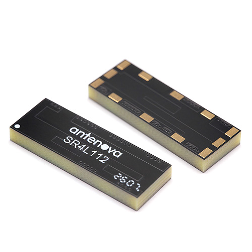
- The SR4L112 Aurata is a 28mm surface-mount FR4 antenna covering principal global LTE bands.
- The design is intended for long, narrow PCBs used in meters, trackers, sensors, and monitoring equipment.
- Final RF performance will depend on host-board geometry, enclosure materials, nearby components, and integration testing.
Antenova has expanded its embedded cellular portfolio with Aurata, a surface-mount antenna designed to provide global 4G and LTE coverage on long, narrow printed circuit boards.
The SR4L112 is manufactured from FR4 laminate and measures 28mm by 10mm by 3.3mm. Direct soldering to the host PCB and tape-and-reel packaging support automated placement across prototype, pilot, and volume production.
Frequency coverage extends from 698MHz to 960MHz, 1710MHz to 2170MHz, 2300MHz to 2400MHz, and 2500MHz to 2700MHz. The ranges encompass LTE 700, GSM 850 and 900, DCS 1800, PCS 1900, WCDMA 2100, LTE Band 7, and LTE Band 40.
Typical efficiency is specified at 67% across 698MHz to 960MHz, 66% between 1710MHz and 2170MHz, 57% across 2300MHz to 2400MHz, and 68% from 2500MHz to 2700MHz. Operating temperature extends from -40°C to 140°C.
IoT sensors, smart water, electricity and gas meters, telematics, asset trackers, machine-to-machine equipment, and remote-monitoring systems form the principal applications. Many use an elongated PCB because the enclosure is built around a pipe, cable, battery, vehicle surface, or restricted equipment compartment.
Aurata is positioned on the short edge of the board and requires clearance in five spatial directions. Ground plane is excluded directly beside the antenna, giving the radiating structure the electrical space required to operate across its supported bands.
An SR4L112-EVB-1 evaluation board is available for measurement and integration work before the antenna is transferred into a production layout.
The host product forms part of the antenna
An embedded cellular antenna cannot be assessed independently from its PCB and enclosure, since board length, ground-plane geometry, battery position, connectors, displays, cables, shielding, and nearby metal alter current distribution and resonant behaviour.
Although the long, narrow format accommodates one common mechanical constraint, the specified clearance still has to be preserved. Moving a battery, adding a shield can, or routing a cable through the keep-out region can reduce efficiency or detune an antenna that performed acceptably during early development.
Low-band operation is particularly sensitive because wavelengths around 700MHz to 900MHz are large relative to the component and most IoT enclosures. The host ground and antenna operate together, making PCB dimensions and product construction part of the effective radiating system.
Efficiency influences battery life as well as communications range. A poorly integrated antenna can force the modem to transmit at higher power or repeat messages more frequently, while prolonged network searches and failed registration attempts add further energy consumption.
Smart meters and remote sensors often operate in cabinets, basements, plant rooms, vehicles, or equipment surrounded by metal and masonry. Free-space measurements therefore need to be followed by testing in the completed enclosure and representative installation environment.
Provisioning technology develops alongside the physical radio design, with SGP.32 eSIM evaluation supporting more flexible network management. Neither subscription flexibility nor modem performance can compensate for an antenna unable to establish a reliable link.
Power consumption is similarly connected to maintenance, and battery replacement has emerged as a constraint on industrial IoT deployment. Antenna efficiency, network behaviour, reporting intervals, and low-power firmware therefore need to be developed as one system.
Verification should include conducted feed-point measurements, over-the-air testing, total radiated power, receiver sensitivity, coexistence, and production tolerance. The final battery, enclosure, cables, display, coatings, seals, and mounting arrangement all need to be present when performance is confirmed.
Temperature, moisture, adhesives, protective coatings, and mechanical variation may shift dielectric conditions or bring material closer to the antenna than intended. Environmental testing should consequently be followed by RF measurement rather than treated as a separate qualification activity.
Aurata provides a compact route into global LTE and LPWA designs where a wider antenna cannot fit the available board. Reliable integration will still depend on treating the antenna, PCB, modem, enclosure, and installed environment as a single RF system.