IN Brief:
- RMS 3D rotates the device around two axes to measure a complete spherical radiation pattern.
- Configurations cover frequencies from 370MHz or 600MHz up to 4GHz or 6GHz for sub-6GHz wireless applications.
- Time-domain and redundancy processing reduce the influence of environmental reflections when measurements are made outside an anechoic chamber.
Saelig has introduced the MegiQ RMS 3D antenna measurement system, bringing automated full sphere radiation characterisation into a conventional laboratory environment without requiring a large anechoic chamber.
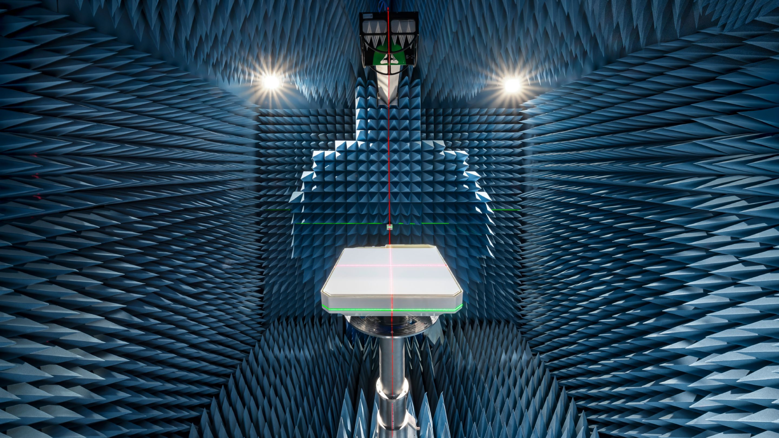
A motorised turntable rotates the device under test around two axes so the system can sample radiation around the complete sphere rather than relying on a few separate antenna cuts. The resulting data can be used to calculate total radiated power, total isotropic gain, peak gain and antenna efficiency while exposing lobes and nulls that might not appear in one or two measurement planes.
Antenna behaviour is inherently three dimensional because the finished product influences the radiating structure. The PCB, enclosure, battery, cabling and nearby components can all alter current distribution and therefore the direction and strength of the radiated field. A design that looks acceptable in one plane can still contain a null or unexpected lobe elsewhere around the device.
Automating both axes also improves repeatability. Manually repositioning a product between measurements can alter cable routing, orientation or distance from the receive antenna. The MegiQ turntable keeps the movement under software control and supports devices weighing up to 7.5kg, with cable routing intended to reduce changes in the test arrangement as the product rotates.
Available configurations cover lower frequency limits of either 370MHz or 600MHz and upper limits of 4GHz or 6GHz. That range includes common sub-6GHz cellular, Wi-Fi 6E, Bluetooth, LoRa and industrial or IoT radios. The system can acquire several frequencies during one rotational scan, allowing engineers to compare broadband performance and harmonic radiation without repeating the complete mechanical sequence for every frequency.
Measurements made in an ordinary room face a problem that an anechoic chamber is designed to suppress. Radio energy reflects from walls, floors, ceilings and nearby equipment, so the receiver can see several propagation paths in addition to the direct field from the device. Those reflections can alter measured amplitude and apparent pattern shape if they are treated as part of the antenna response.
MegiQ uses specialised measurement antennas together with time-domain and redundancy processing to reduce those multipath effects. Saelig says the method allows operation in laboratory spaces as small as about 12 × 12 × 9ft, with stated base measurement accuracy of ±1dB and repeatability of ±0.5dB after calibration at the factory.
Those specifications do not make a normal room physically equivalent to an anechoic chamber. The system instead measures and processes the received signal so reflections have less influence within the supported conditions. Engineers still need sufficient clearance around the turntable, a controlled mechanical arrangement and consistent cabling if measurements from different design revisions are to be compared reliably.
The receiver measures horizontal and vertical linear polarisation and can derive right-hand and left-hand circular polarisation together with axial ratio. Polarisation behaviour matters because two radios can show acceptable total power while coupling poorly if their antenna polarisations do not align under the orientations encountered in service.
Software supplied with RMS 3D controls movement, records received power, displays 3D patterns and produces measurement reports. Calculations include radiated power, EIRP, ERP, field strength, gain and efficiency. Saelig says the software is supplied without a separate licence fee.
Antenna developers often use an external chamber for regulatory testing or final validation, but booking that facility for every enclosure or PCB change can slow development. A laboratory system on site can be used earlier to compare revisions, identify an unexpected null or evaluate the effect of a changed housing before a formal chamber session.
RMS 3D is positioned as an engineering measurement system rather than a replacement for every accredited test method. Its role is to provide full sphere data during development using a smaller laboratory setup, provided the reflection processing and controlled fixture deliver the repeatability required for the comparison being made.