IN Brief:
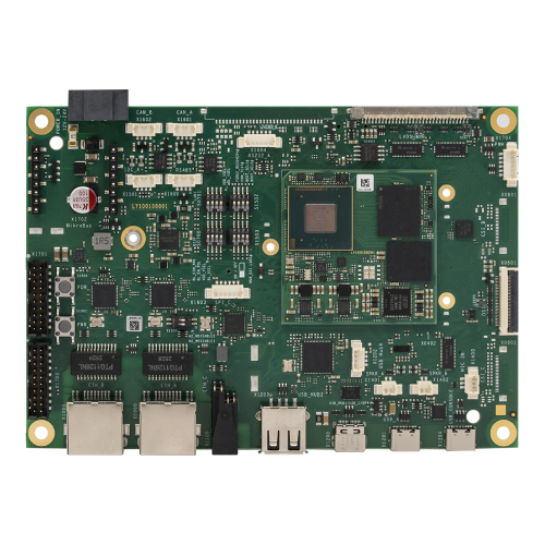
- The OSM-SB-EP5 supports OSM 1.2 Size-S, Size-M, and Size-L compute modules within a 146 × 102 mm development board.
- Connections include two Gigabit Ethernet ports, single-pair Ethernet, CAN, serial communications, MIPI camera interfaces, and M.2 expansion.
- The board is available for evaluation, with supported interfaces and functions determined partly by the installed compute module.
Tria Technologies has introduced the OSM-SB-EP5, a development and evaluation platform for embedded systems based on the Open Standard Module specification. The carrier board exposes industrial communications, camera, display, and peripheral interfaces, allowing developers to test a compute module before completing an application-specific hardware design.
The platform supports Size-S, Size-M, and Size-L modules conforming to OSM version 1.2. It measures 146 × 102 mm and provides connections for Gigabit Ethernet, single-pair Ethernet, CAN, RS-485, USB, MIPI camera interfaces, and display outputs. Expansion facilities include an M.2 Key E socket and a mikroBUS connector.
Tria has made the platform available for evaluation and is demonstrating it at electronica 2026 in Munich. The board is intended to provide a common hardware environment for comparing processor modules and validating the peripheral connections required by a proposed embedded product.
OSM differs from conventional computer-on-module architectures in its mechanical integration. Rather than using a removable board-to-board connector, an OSM compute module has solderable contacts that can be attached to the carrier through an automated assembly process.
The standard defines several module sizes. Size-S measures 30 × 30 mm, Size-M measures 45 × 30 mm, and Size-L measures 45 × 45 mm. Larger modules provide additional space and contacts for processors, memory, and supporting circuitry, although their available functions depend on the particular module design.
Tria’s evaluation board accommodates the three specified sizes, allowing compatible modules to be assessed using a shared carrier. Its interface arrangement is particularly useful during early development, when a processor has been shortlisted but the final hardware architecture has not yet been fixed.
Two Gigabit Ethernet ports provide conventional wired networking through RJ45 connectors. A separate single-pair Ethernet interface supports 1000BASE-T1 through an associated physical-layer device, providing an additional option for systems using a more compact cable arrangement.
Ethernet interface selection depends on the communication environment. Conventional twisted-pair networking is widely used for equipment connections, while single-pair Ethernet can suit installations where cable dimensions, connector arrangements, or the physical positioning of connected devices require a different approach.
The board also provides two CAN interfaces and UART connections supporting serial communication arrangements, including RS-232 and RS-485. These interfaces allow control electronics to communicate with industrial devices, sensors, and external modules that use established field-level communication methods.
The presence of a physical interface does not establish support for every associated communications protocol. For CAN FD and other functionality, the processor module, peripheral controller, firmware, and chosen software stack must provide the required capabilities.
Developers can also access GPIO, I²C, SPI, analogue inputs, and pulse-width modulation signals. Such interfaces are used to connect application-specific sensors, control circuitry, and supporting devices, making it possible to evaluate peripheral behaviour before committing to the production carrier layout.
The M.2 Key E socket provides additional expansion through interfaces including PCIe, SDIO, USB, and serial connections, depending on the fitted module and expansion device. Wireless networking can be evaluated where compatible hardware and software are available.
For embedded vision applications, the carrier exposes two MIPI CSI camera interfaces, with an additional interface available in some configurations. MIPI CSI is designed for high-speed transfer of camera data to a processor, where software and hardware resources must accommodate the selected image resolution and capture rate.
Display connections include LVDS and MIPI DSI arrangements. The board can therefore support development systems combining image capture, local processing, and a visual interface, provided the chosen OSM module implements the necessary display and camera functions.
Running these peripherals concurrently can place competing demands on processor and memory resources. Camera traffic, graphics output, networking, and application software may all require access to shared data paths, making early evaluation useful when establishing the system’s performance requirements.
USB connectivity includes Type-C and Type-A connections, while debugging facilities provide JTAG and USB-to-serial access. A microSD socket, Quad SPI NOR flash, and real-time clock battery provision support storage, boot configuration, and development tasks.
The carrier accepts a nominal 12–24 V DC supply. Its published operating temperature range is −25°C to +85°C, although the capabilities and temperature rating of the complete assembly also depend on the installed OSM module and other fitted components.
Tria identifies industrial control, robotics, edge computing, medical equipment, and embedded vision among the applications suited to the platform. Moving from the evaluation board to a production carrier will still require validation of signal integrity, power distribution, electromagnetic compatibility, thermal performance, and mechanical integration.
The OSM-SB-EP5 provides a means of starting that work on a defined hardware platform. Development can begin with processor and interface selection while the final carrier design is refined around the electrical and mechanical requirements of the intended product.