IN Brief:
- The QPX0252 beamformer covers 7.9 to 12 GHz and supports four antenna elements with dual receive and single transmit beams.
- Its output can directly drive compatible Qorvo front end modules, removing a separate driver amplifier from the lattice.
- Companion bias and switch-control devices support transmit and receive switching in less than 100 ns.
Qorvo has introduced an X-band architecture centred on its QPX0252 beamformer, combining transmit drive, dual-beam receive functions and supporting control devices within the restricted lattice spacing of active electronically scanned radar arrays.
The CMOS QPX0252 operates from 7.9 to 12 GHz and supports four radiating elements, with a single transmit beam and two receive beams. Six-bit phase and gain control adjust the amplitude and phase presented to each antenna path, while SPI control gives the wider radar system access to beam steering and configuration functions.
Each radiating element in an AESA has to maintain controlled physical spacing from its neighbours so that the array can steer beams without creating unwanted grating lobes across its intended scan range. That geometry limits the PCB area available behind every element for the beamformer, amplification, bias control, switching and interconnect.
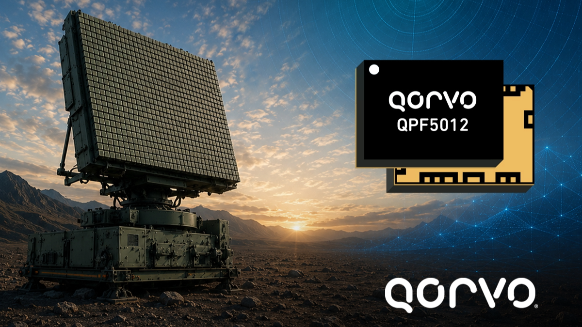
Qorvo has given the QPX0252 sufficient transmit output to drive compatible front end modules directly. Removing an intermediate driver amplifier cuts the number of active devices within the lattice and eliminates another RF interface, power rail and source of heat. The beamformer is intended to work with devices including the company’s QPF5012, which integrates transmit and receive functions for X-band phased array radar.
The QPF5012 was introduced earlier in 2026 as a compact 10 W X-band front end module. The October architecture extends beyond that individual device by connecting beamforming, amplification, bias control and switching across a four-element group.
On receive, the front end module establishes a low system noise figure before the signal reaches the beamformer. The QPX0252 can then operate in a high-linearity mode to increase the signal level the cascaded chain can tolerate before compression.
Input P1dB defines the point at which gain departs materially from its linear response. Increasing that threshold gives a receiver more room to handle strong signals without compression, which is useful when weak radar returns have to be detected while other high-level RF energy is present in or near the operating band.
The QPX0252 also supports two simultaneous receive beams. Multiple beams from the same set of antenna elements can allow receive resources to be allocated differently from the transmit path, although the capability of the completed radar still depends on the digital processing, timing and aperture architecture behind the RF hardware.
Companion Qorvo devices provide gate bias, drain bias and RF switch control around the front end, with the company specifying transmit and receive switching in less than 100 ns. Rapid switching reduces dead time between the high power transmit state and the sensitive receive interval used to capture reflected signals.
The receive chain must remain protected while the transmitter is active, yet excessive delay before returning to receive mode can reduce the system’s ability to observe shorter-range returns. Integrating the switching and bias controls around known beamformer and front end devices gives the designer a defined starting point for sequencing those operating states.
The QPX0252 is supplied in an FC-CSP package and includes Qorvo’s Zero-Cal function for reducing array calibration time, together with quiet mode, health monitoring and fast beam-steering functions. Samples and evaluation kits are available, while compatible X-band front end modules are already in production at several power levels.
The October launch is therefore an architecture rather than an isolated beamformer IC. Available lattice area does not increase when more RF functionality is required, so reducing the number of separate driver, control and switching devices can materially affect how much electronics can be fitted behind each antenna element.