IN Brief:
- Cliff has redesigned its USB 2.0 and USB 3.0 panel feedthrough couplers across four connector orientations.
- The replacement construction uses PCB-mounted connectors in a moulded housing, reducing depth by up to 10mm depending on the model.
- Production changes are being phased in as existing stock is exhausted, with revised drawings and CAD data available to customers.
Cliff Electronics has redesigned its USB 2.0 and USB 3.0 panel feedthrough connectors, cutting the overall depth by up to 10mm on certain variants. The British manufacturer now mounts the internal USB connectors directly to a PCB inside a moulded plastic housing, replacing hand-soldered wires and overmoulding. The updated constructions are entering supply through a phased production change.
The changes cover A-to-A, A-to-B, B-to-A, and B-to-B USB feedthrough combinations. Each device provides a connection on either side of a panel, allowing a USB interface to be accessed from an enclosure without passing a loose cable through it. Cliff says the function and established performance are unchanged; the revision concerns mechanical depth, assembly construction, and materials rather than a different USB signalling specification.
A panel-mounted coupler must fit the available space behind its mounting face without interfering with cable bends, fixing hardware, and neighbouring equipment. Compact test instruments and industrial cabinets can have little clearance beyond the rear socket, particularly once the mating plug and its strain relief are installed. Reducing the connector body helps only if the finished cable assembly still fits the allocated volume.
The 10mm reduction is the largest figure stated for the family, not an dimensional change across the range. An engineer replacing an existing part therefore needs the drawings for the exact model and rear socket arrangement, including the space required for a plug and cable. Similar front-panel appearances do not establish identical installation envelopes.
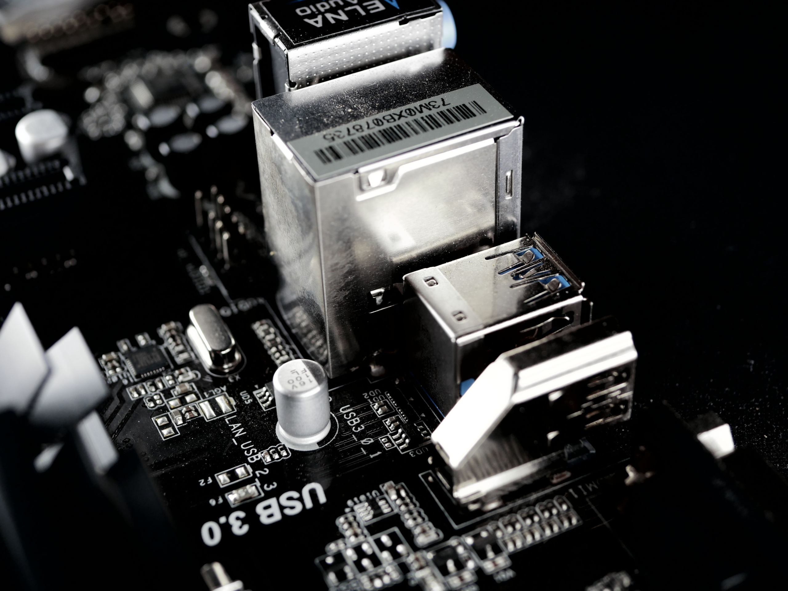
Previous designs linked the two connector ends with short, hand-soldered wires inside an overmoulded body. The revised parts place the connectors on a PCB, moving the electrical interconnection onto defined copper traces and fixing the socket geometry within a purpose-made housing. That may improve assembly consistency, although the channel behaviour depends on the PCB routing and the mechanical tolerances achieved in production.
USB 2.0 and USB 3.0 links have different electrical demands. USB 2.0 high-speed signalling depends on a differential pair with controlled channel characteristics, while USB 3.0 introduces additional high-frequency transmit and receive pairs. Connector transitions, printed-circuit traces, shielding, and the cumulative insertion loss of the entire channel can affect whether the interface works reliably with the chosen cables and host electronics.
A short PCB route does not automatically outperform a short wired connection. Dielectric properties, return current paths, trace geometry, vias, and the transition into the socket can affect high-frequency performance, particularly on USB 3.0 links. Cliff states that the redesign retains established functionality, but the release does not include insertion loss plots, signal eye measurements, or separate certification evidence for the new construction.
The revised housings use plastics meeting UL 94 V-2 or a higher flammability classification, according to Cliff. UL 94 assesses material behaviour in a specified flame test; it is not a complete fire-safety approval for an installed machine or cabinet. The relevant equipment standard and the enclosure’s wider material and electrical design still determine the system-level requirements.
Production test stations, instrumentation enclosures, and industrial control cabinets commonly use panel feedthroughs to bring communications ports to an accessible face. Repeated mating, vibration, and external contamination can affect the service life of such connections. The November redesign does not establish an improved ingress protection rating, mating cycle figure, or operating temperature range, so those limits still need to be verified from the selected component’s documentation.
Revised drawings and three-dimensional CAD models are important for customers with fixed panel cut-outs and tightly controlled bills of materials. Even when a connector fits the existing opening, its rear geometry, socket alignment, and surrounding housing can affect assembly access or neighbouring components. Mechanical checking is therefore necessary before a replacement is accepted into an existing enclosure design.
Cliff will continue supplying the earlier versions while stocks remain, then phase in the revised construction. The company intends to keep individual customer orders consistent with one version where possible during the transition. Manufacturers running repeated builds should record the delivered revision and determine whether fixture instructions, incoming inspection, or the assembly drawing require changes.
The update applies to the company’s USB feedthrough family, not its full range of Ethernet, RF, audio, and other panel connectors. On the specified variants, the documented change combines reduced body depth with a PCB-based internal connection and revised plastics. Mechanical suitability and electrical behaviour must still be assessed against each model’s datasheet and the complete installed USB channel.