IN Brief:
- The M704 is rated for applications up to 4,000 V AC and supports automated PCB mounting.
- The M705 supports applications up to 2,500 V AC and operates at temperatures up to 180°C.
- Both assemblies use 10kΩ NTC elements with ±2% resistance tolerance and a B25/100 value of 3,988K.
TDK Electronics has expanded its negative temperature coefficient sensor range with two probe assemblies intended for equipment operating at elevated electrical voltages. The M704 supports applications rated up to 4,000V AC, while the M705 is specified for up to 2,500V AC. Both are intended for temperature measurements in power electronic equipment including uninterruptible power supplies, charging stations and photovoltaic inverters.
The assemblies share the same nominal sensing characteristics but differ in their mounting arrangements and environmental limits. Both use a 10kΩ thermistor at 25°C, a B25/100 value of 3,988K with ±1% tolerance, and a resistance tolerance of ±2%. The M704 is specified for temperatures from -40°C to +125°C, whereas the M705 extends the upper limit to +180°C.
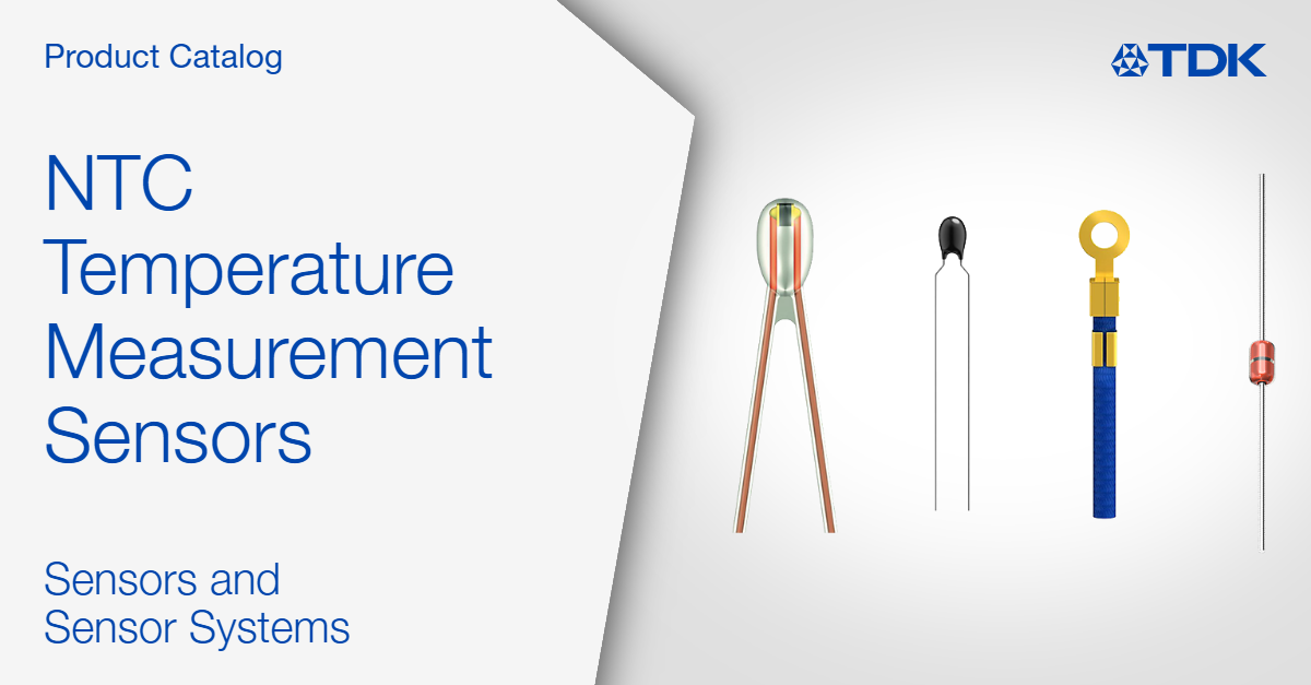
TDK supplies the M704 in a compact plastic case with 3.5mm lead spacing, intended to support automated printed circuit board assembly. The spacing and form factor allow the sensor to be incorporated into an established manufacturing process where a component can be placed on a board. Its stated voltage capability does not, on its own, establish the clearance, insulation and protection requirements of the complete installation.
The M705 uses a metal-tag ring lug, allowing it to be fastened against a suitable mechanical surface. TDK reports a thermal time constant of approximately 6.2 seconds when the sensor is mounted on a metal plate. The figure describes response under a particular mounting condition, not a universal time constant for every fastening arrangement or material. Thermal interface quality and the location of the sensor relative to the component being measured can alter its response.
Negative temperature coefficient thermistors change resistance as temperature varies. In these devices the resistance falls as the sensing element becomes hotter, allowing an external circuit to calculate a corresponding temperature. R25 specifies the nominal resistance at the 25°C reference point, while the B value helps describe the relationship between resistance and temperature over the indicated range. A measurement circuit must use a suitable conversion method rather than treating the output as a direct digital temperature reading.
Resistance tolerance and B-value tolerance place limits on the precision available from the element itself. The system’s overall accuracy also depends on the measuring circuit, calibration, electrical excitation and the thermal relationship between the sensor and the target surface. The October product announcement does not provide a system-level temperature error that can automatically be applied to a finished inverter or power supply.
In a power converter, switches, magnetic components, capacitors and electrical connections can operate at different temperatures as losses change with loading. A sensor mounted on a printed circuit board may track the local board environment, while a mechanically attached probe can measure a particular metal surface more directly. Neither configuration necessarily identifies the hottest location in the equipment unless placement has been established through thermal testing.
The different mechanical packages therefore address different assembly requirements. The M704 is suited to designs where the sensor can be incorporated into automated PCB production, while the M705 provides a screw-mounted interface where thermal contact to a mechanical part is required. The latter’s higher maximum temperature is useful only if the other materials and connections in the assembly also meet the intended operating conditions.
Equipment operating at high electrical potentials creates additional requirements around measurement isolation and safe handling. The specified application voltage indicates the range for which the sensor assemblies are offered, but it is not a blanket approval for any wiring arrangement or insulation strategy. Designers still need to assess separation distances, fault conditions and the interface between the temperature sensing circuit and lower-voltage electronics.
TDK lists power supplies and UPS installations in data centres, electric charging infrastructure, photovoltaic inverters and other power electronic systems among the intended applications. Those systems may use temperature feedback to adjust loading, trigger protective responses or supervise cooling equipment. Whether a particular sensor is suitable depends on its thermal response and installation position as well as its nominal voltage and temperature specifications.
The M704 and M705 broaden the available installation options rather than changing the underlying method of resistance-based temperature measurement. The selection is between a higher application voltage with automated board mounting and a higher maximum operating temperature with a metal mounting tag. TDK has published ordering codes B57704M0103A001 and B57705M0103A001 for the two assemblies, respectively.